- Edited
MindRacer V1.2 pinout map
Interface board v1.0 pinout map
Hello,
Thanks for your email. I figured out to use companion computer, actually UART_TX and UART_RX (ON J8) are needed, not the usb part. Now I can connect mindracer to gcs without usb cable under raspberry pi. But some errors occured, I am trying to figure that out. Thanks.
zhanghaijason
You are welcome.
Use J8(Telem2) is also a nice option, more convenient than USB so can adjust baud rate flexible and avoid changing startup rc scripts. Just pay attention as no flow control line on Telem2 so mind your data rate setting not to exceed the processing speed of CPU on both side.
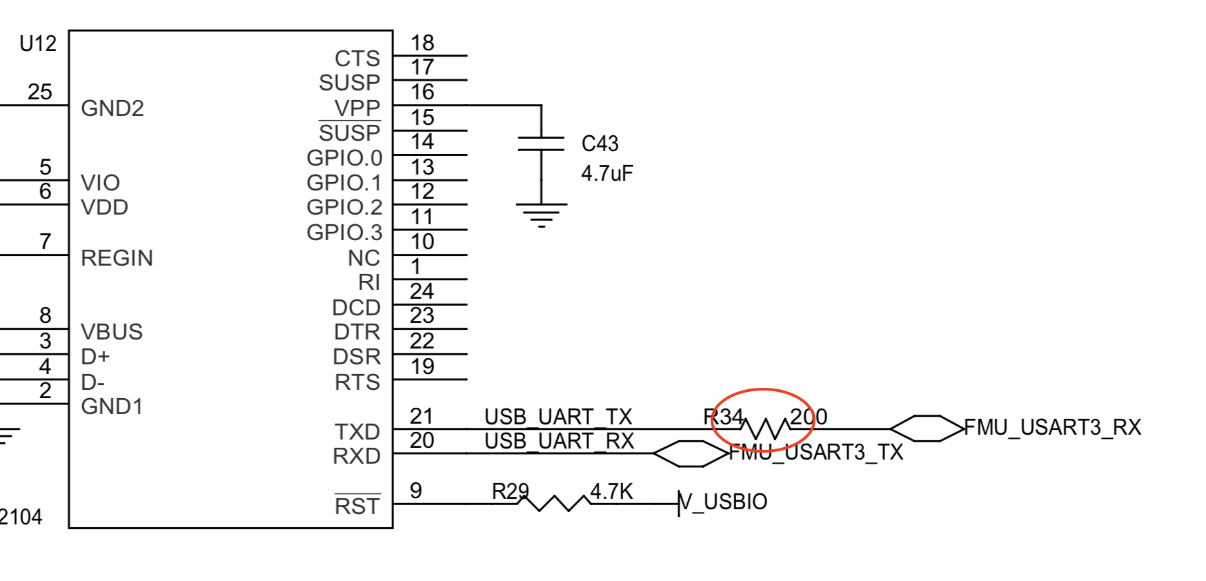
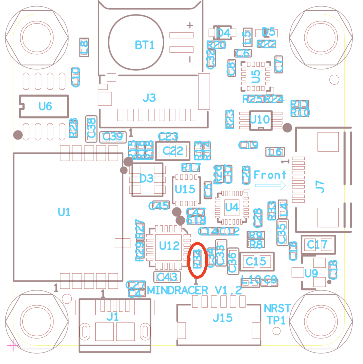
rolandash
Hello,
As mentioned above, I have other issues when interface mindracer with raspi. Now I guess the UART_RX on j8 is not working. It is because first my raspi can receive the heartbeat of mindracer, can receive the IMU data from mavros. But gives warnings such as "VER broadcast request timeout" and finally error "WP timeout". And it gives the same warnings and error information even I unplug the RX on mindracer. So that is how I believe RX on mindracer is not working. Does that sound resonable to you? If yes, is there an easy way to fix it?
Thanks.
It is less possible that 'RX' not working. It is just a single line led out from processor pin.
Are you sending something from raspi to Mindracer? What kind of protocol you are using and what respond you are expecting? These error messages does not look like related to UART communication.
Usually for UART communication you have no way to know if the connection is good or not as no error message will be emitted, until the peer specifically reply your command.
It is the tutorial to use indoor motion tracking system and companion computer to control the drone. I think raspi is sending position and orientaion data to mindracer through uart in ROS environment.
The protocal is the mavros (I don't know if it is a kind of protocol or not), I guess there are many messages printed out in mavros other than usual uart communication.
What I expect is that the GCS should be able to receive the GPS data as I can receive it in raspi and realy this data to mavros/pose topic. And it should allow me to switch the flight mode into position. However, neither can be achieved. And that is the only error I got. So I guess mindracer failed to receive the fake gps data from motion tarcking system from UART.
The tutorial I refer to is https://risc.readthedocs.io/1-indoor-flight.html
Thanks.
Or is that because the UART voltage level? I know raspberry pi uses 3.3V. But I searched that stm32 is also 3.3v so directly connect them should work.
OK I see.
In that case J8 RX may be possibly not working as you expected, as J8 UART RX is actually shared by USB2 and J8.
J8 is configured to be used as OSD with output only and USB2 is used to connect to external computer.
A few solutions below you can try:
Still switch back to USB2. It is the recommended interface with an onboard computer. Just need to make a USB-A to GH adaptor cable.
[upl-image-preview url=http://www.club.mindpx.net/assets/files/2019-07-27/1564211656-644640-screen-shot-2019-07-27-at-30508-pm.png]
Use Telem1 instead. This should work the same way. But you may need to change port baudrate setting in rc script and recompile the PX4 source code.
If you really want to use J8, then USB port needs to be disconnected by remove the R34 resistor on MindRacer board. Note this way potentially risk and you can not use USB2 port then.
Hi,
Just two more questions about the solution 1 and 3
Soldtion 1 is just directly soldering USB wires to the GH adaptor wires? I tried this but the raspi cannot detect the new USB device, someone says it is because the low current supply. I will try again when I receive the new power supply for raspi
Solution 3 means after removing R34 I can directly use the RX and TX pins on J8, right?
Another point you need to confirm is if your software driver supports CP2104 USB bridge chip on raspi. It is supported by Linux & Android by default, but I am not sure what software you are running on raspi.
Hello,
Just let you know that method 1 works with the MRPDB. Now the onboard pi computer is working. Thanks.
Glad to know it. Have fun flying!
rolandash Hi Rolandash, I am having USB issue for this onboard computer again. Now my raspberry pi cannot detect the USB device(mindracer). I followed the configuration for onboard computer and used a USB cable to connect raspi and mindracer with USB2. But when I use ls /dev on Raspi, it cannot show USB0. Of course when I run roslaunch mavros .. fcu:URL:dev/ttyUSB0:921600, it shows no such file or directory.
I haven't used it for more than 7 months since last time I succeed. Then I purchased a new mindracer (because my last one was fired due to short circuit) and assembled them. I even soldered another USB cable, it still cannot detect the mindracer. And raspberry pi is powered from a 5V BEC not from USB. Do you have any idea what is the possible reason? Now I have TFmini on GPS port, PMW3901 on U2 port (as you instructed in another post). Will those sensors influence it?
I think it might be the raspi-config. I don't remember it I enable serial communication or not. The operating system is a an image I saved before. I think it should enabled the serial. But I will double check tomorrow.
A straight way to separate the problem is to connect the MindRacer to QGC through USB2 port. If succeed then it shows the USB port works fine. The problem is mostly on Raspi side.
rolandash Hi Thanks for the tip. It turns out it is the USB2 not working. Is it because of the expansion board or the mindracer? Which one do you think is more possible? And could you teach me the 2nd method using telem 1 if when you have time? Thanks.
zhanghaijason
But the problem now is Telem1 seems not working properly?
I think better to make sure Telem1/2 not been already physically damaged first.
rolandash As we talked before in the other post, when using mindracer to power the TFmini, Telem1 can work with TFmini (I would say 70% success rate) when only using USB to power the mindracer. But definitely not working when using battery and the MRPDB to power the mindracer.
Then I followed your advice to use the MRPDB 5V BEC to power the TFmini.
Now I use multimeter tested the output of Telem1 when mindracer is powered. VCC 5.08V, FMU_TX 3.23V, RX 3.23. Telem2 VCC 5.08V, TX 2.9V, RX 3.2V. Are there anything else I can do to test the Telems? And NO OUTPUT from USB2.
What do you mean by "NO OUTPUT" from USB2?
No VCC voltage at all?